
A number of the applications will be discussed in depth below. For applications that are less prevalent, some background material will be provided and for others, it will just be noted as possible use.
Self-Heated Applications:
Some of the different types of applications that utilize the self-heated characteristics of the PTC thermistor include:
- Self-Regulating Heaters
- Over-Current Protection
- Motor Starting
- Constant Current
- Arc Suppression
- Time Delay
- Liquid Level / Air Flow
Standard Heaters:
If a voltage is placed across a PTC, the current will flow and begin to heat the part. Since most PTCs are in their NTC region when first energized (see Figure 12), heating causes the resistance of the part to drop. The decreasing resistance, in turn, causes more current to flow which heats the part still further. If the voltage is high enough, the unit will self-heat until it passes into the PTC region of resistance.
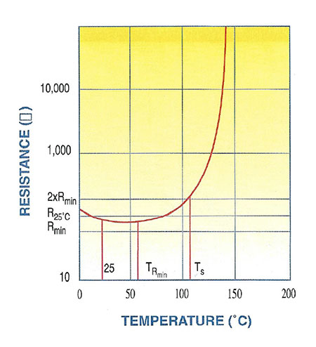 Fig 12: Resistance vs Temperature
 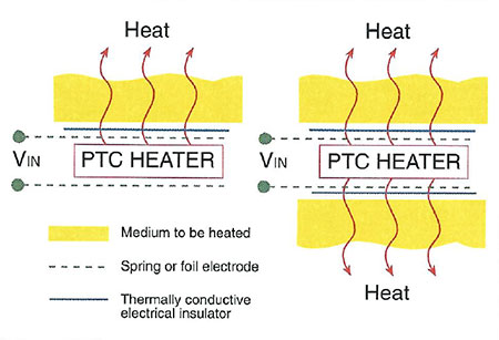 Fig 13: Heater Transfer
Once in the PTC region, this ceramic element exhibits a truly remarkable feature. It reaches the point where I2R heat generated by the part is sufficient to make up for the loss of heat to the ambient. In this situation, the device is in equilibrium. If it starts to decrease in temperature, its resistance will decrease drawing more current and countering the cooling tendency. Conversely, any tendency to increase its temperature meets just the opposite effect. In this condition, the PTC is auto-stabilized at a fixed temperature.
Even with regards to voltage changes, the constant temperature mechanism will be effective. If the operating voltage increases, the PTC initially consumes more power but, as a result, its temperature increases, and thus the current becomes stabilized at a lower level. The performance of the PTC is not proportional to the square of the voltage as in the case of ohmic resistance. In other words, the power consumed is nearly independent of voltage over a wide voltage range.
Design considerations for Standard Heaters can be found here.
PTC Over-Current Protectors:
PTC thermistors are semiconducting ceramic devices that exhibit the ability to switch from a low resistance state to a high resistance state depending upon their body temperature. PTC ceramic thermistors have been proven reliable and effective over many years of use in a variety of over-current applications. Ceramic PTCs, unlike other PTC technologies, return to their same initial resistance at 25°C after being subjected to a fault condition. Ceramic PTCs can be switched again and again and will return to their initial value and are not subject to hysteresis. Ceramic PTCs can be sorted into very tight resistance groups for matched pair applications. For over-current applications, the PTC element is normally placed in series with the component that requires over-current protection as shown in the figure below:
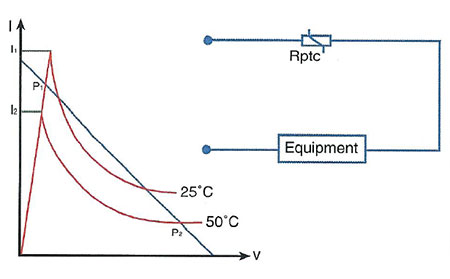 Fig 14: Over-Current Protector Circuit
The following is a description of how the PTC functions as an over-current protector:
- Under normal conditions, the PTC element has a relatively low resistance value. The current flowing through the part does not provide enough energy to heat the PTC beyond the ambient temperature.
- A short circuit or over-current condition causes I2R heating within the PTC. When its body temperature reaches the Curie Point or Switch Temperature of the material, the PTC transforms into a high resistance element, thereby limiting current to the load.
- Removing the fault condition decreases the current flow and allows the PTC to cool to its normal resistance mode.
Design considerations for Over-Current Protectors can be found here.
Motor Starting:
PTC thermistors can be used to protect the auxiliary starter winding of induction motors or single-phase motors as shown in figure 15.
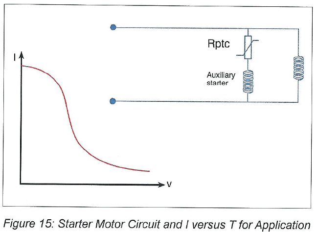
When the circuit is turned on, the PTC has a low resistance and most of the line voltage is applied to the starter winding. After the motor starting, the PTC heats up and switches to a high resistance state. The time for this to occur is determined by the size and resistance of the PTC, as well as the amount of current flowing through the starter winding. When the PTC has reached a high resistance state, the current flowing through it, as well as the starter winding, falls substantially.
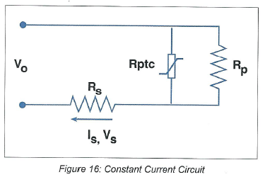
Constant Current:
It is possible to obtain a nearly constant current by connecting a PTC thermistor in parallel with a resistor. The nearly constant temperature of a self-heated PTC results in a circuit that can adjust the current over a wide range of voltages. When the voltage of the circuit is increased, the temperature of the PTC increases slightly which will cause an increase in the resistance of the PTC thermistor and a small decrease in the current through the thermistor compensating for the increase in current through the parallel resistor. The overall current through the load will remain relatively constant over a wide range of voltages. An equation that approximates the current through the load is:
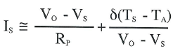
Where:
TS = PTC Switch Temperature (°C)
TA = Ambient Temperature (°C)
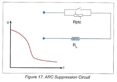
Arc Suppression:
The circuit shown in Figure 17 shows how a PTC is used for arc suppression. When the switch is open, the PTC changes from low resistance to high resistance. The initial low value of the PTC provides for effective arc suppression as most of the voltage is dropped across the PTC. As the PTC switches to its high resistance state, more and more of the supply voltage is transferred to the inductive load.
Time Delay: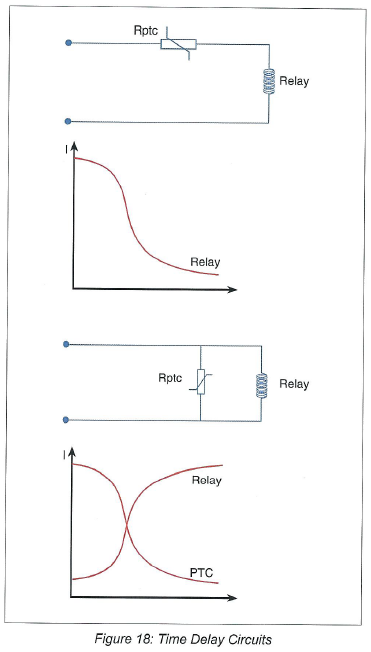
The time needed for a PTC thermistor to switch from its low resistance state to a self-heated high resistance state may be used to provide for a time delay in a circuit. For example, if a PTC is connected in parallel with a relay, the relay will only be energized after the time necessary for the PTC to switch from low to high resistance. When a PTC is connected in series with a relay, the relay would energize immediately and would stay energized until the PTC heats up and increases in resistance. At that point, most of the voltage would be dropped across the PTC and the relay would no longer be energized. The time for the PTC to switch in either case would be dependent upon the resistance and size of the PTC, as well as the ambient temperature and other circuit parameters such as supply voltage and other components in the circuit.
Liquid Level / Air Flow: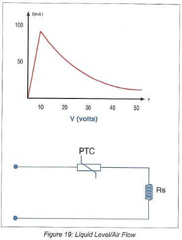
These applications are based on the principle that the dissipation factor of a thermistor, o, changes with respect to changes in the environment surrounding it. This change in o allows the thermistor to either be able to shed more or less heat to its surroundings. See the figure below for a typical circuit configuration for a PTC used as a liquid level or airflow sensor.
In general, a self-heated thermistor in a liquid can dissipate approximately four to six times as much power as it can in the air. Likewise, a self-heated thermistor can shed more heat inflowing air than it can in still air. A good liquid level/airflow design should ensure that the design operates under worst-case conditions. For example, for a liquid level application, the design should function such that the thermistor can dissipate more power when submerged in the hottest liquid than it can when subjected to the coolest air.
Temperature Sensing and Control:
Unlike the NTC thermistor with its ability to sense temperature accurately over a wide temperature range, the PTC thermistor is only useful as a temperature measuring device over a relatively short range of temperatures near the switch temperature. Because the resistance versus temperature characteristic of the PTC thermistor does not lend itself to an equation, most specifications are for the PTC thermistor to be a resistance value at some specific temperature plus or minus some tolerance. When the PTC is being used as a temperature sensor, the amount of current through the PTC must be small so as not to self-heat the thermistor and cause errors. Normally, it is not possible to use a PTC thermistor as a temperature sensor when it is in a self-heated mode of operation.